September 2002 - Page 1
Sunday 1st
Wired most of the dash. Not quite sure how to wire up the hazard warning switch, so that'll have to wait. Turned the electrics on for the first time; nothing melted. Wired up the radiator fan so that it will come on with its own thermostat switch or with a manual override on the dash. Tested the horns that I fitted last week, they're loud!
Fitted the side indicator repeaters.
Decided it would be sensible to fit the front cycle wing brackets before I fit the headlamps. The brackets bolt to the three holes in the hub that originally were used for the brake dust shield. The dust shield bolts from the wheel side whereas the cycle wing bracket bolts from the inside. The problem is that the thread in the holes in the hub do not go all the way through. This left me with two options: I could use thinner bolts and put a nut on the end, or I could tap the thread all the way through the holes. The second option was best, but unfortunately I didn't have a tap. So I made one out of a stainless steel setscrew using an angle grinder. It worked a treat! I'm a bloody genius! Now I can tighten a setscrew from the outside and use two nuts to position the cycle wing bracket perfectly.
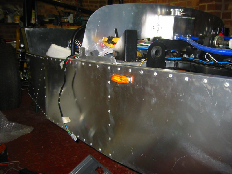
Offside indicator repeater |
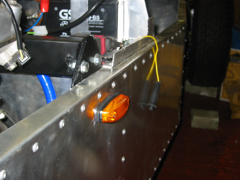
Nearside indicator repeater |
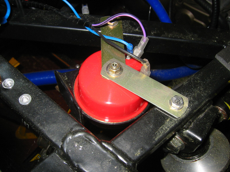
Horn (there's two of these) |
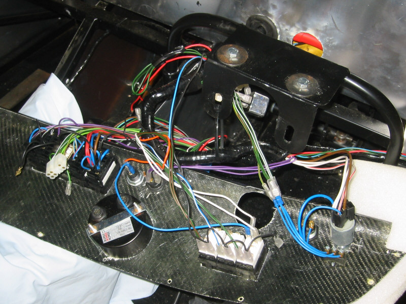
Dash wiring |
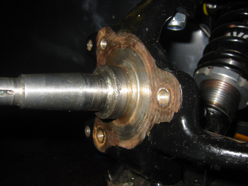
Brake dust shield mounting holes, used for mounting cycle wing brackets |
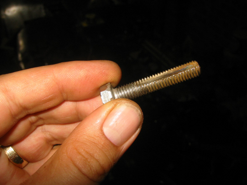
Homemade tap |
Wednesday 4th
Connected up the Stack dash module and played around with some of the settings. Can't wait to see it working on the move.
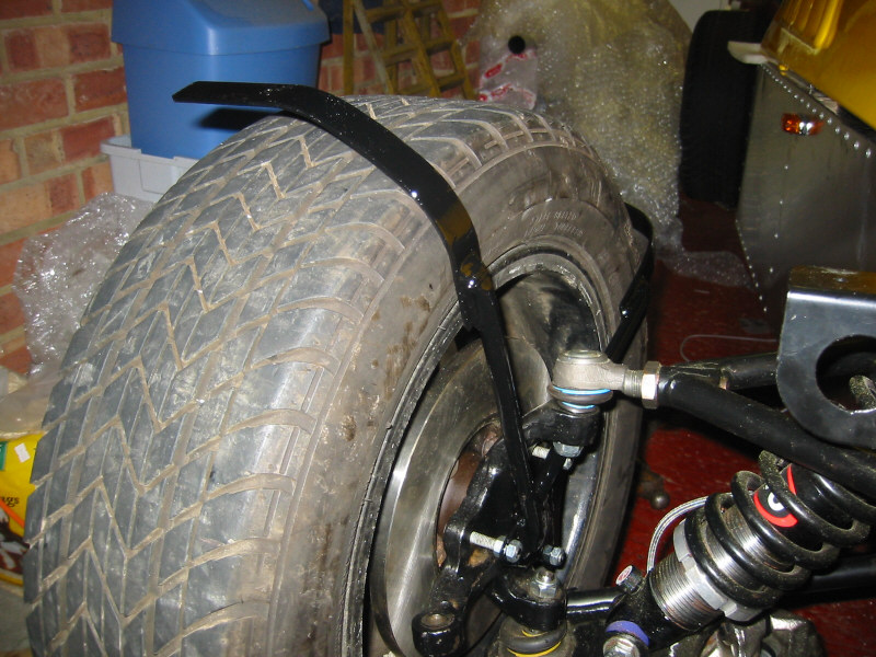
Fitted the front cycle arch brackets to the hubs. The cycle arch mounts are straight and have to be bent to position to suit your wheels and arches. I used a large hammer handle held against the wheel to bend the mounts around. The cycle arches are going to be a tight fit over my wheels though.
I'm going to apply for my SVA test today. This is it!
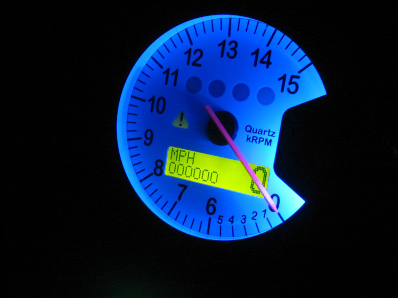
Stack dash illumination. |
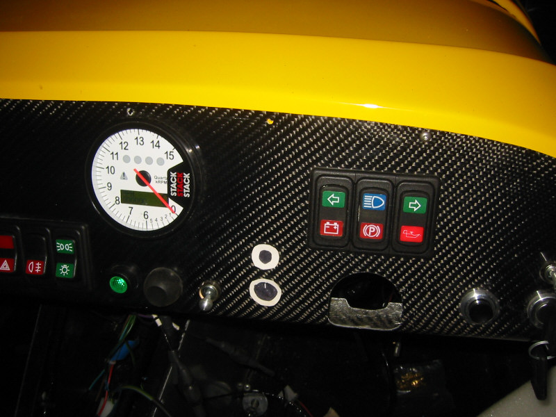
Dash powered up. |
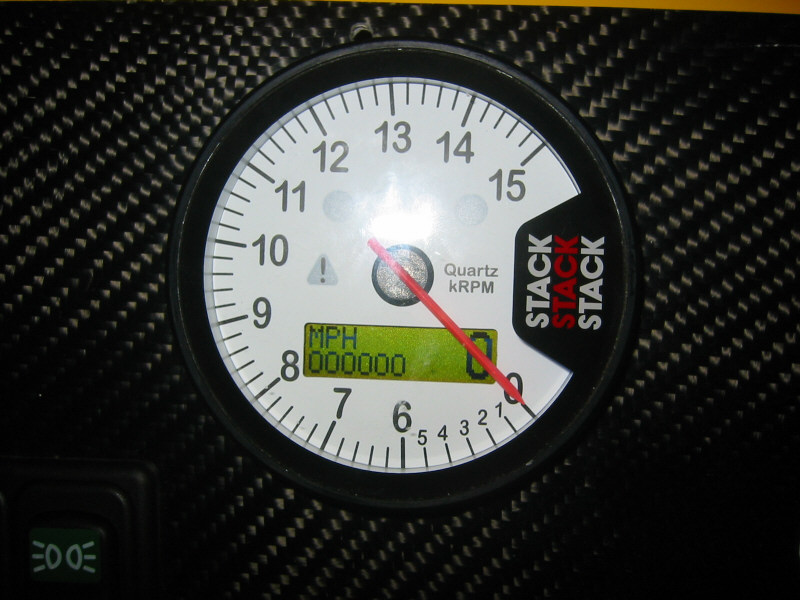
Stack powered up showing odometer and speedo |
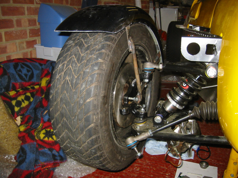
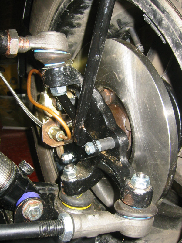
Cycle wing and bracket. Once I've got the position right, I will remove the bracket and paint it. |
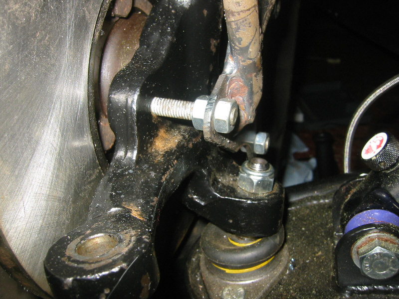
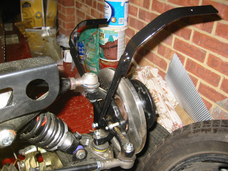
Close-up of bracket mount to hub. The bracket it is held in place by two nuts each on three setscrews fitted through the brake dust shield mounting holes on the hub |
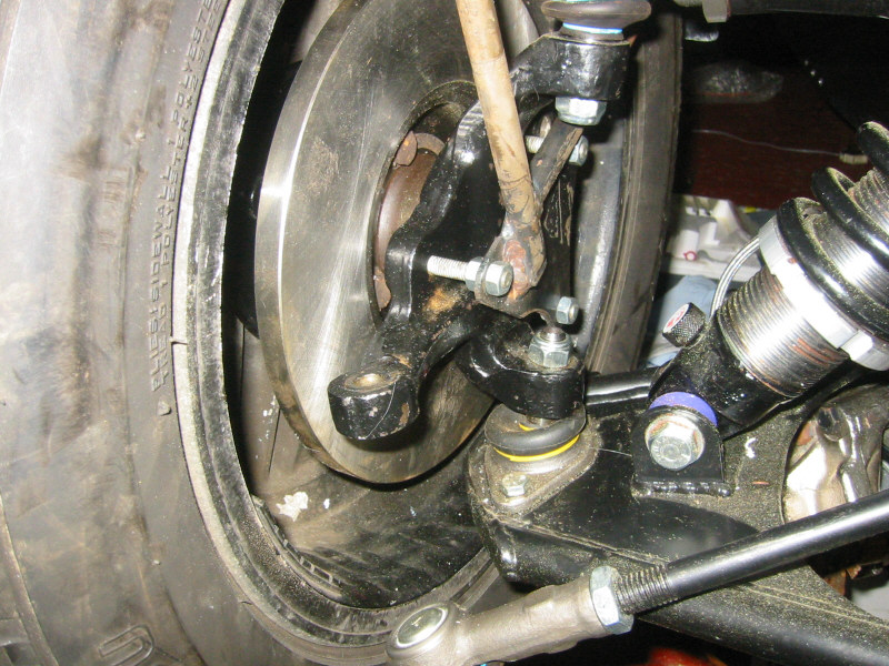
Cycle wing bracket mounting |
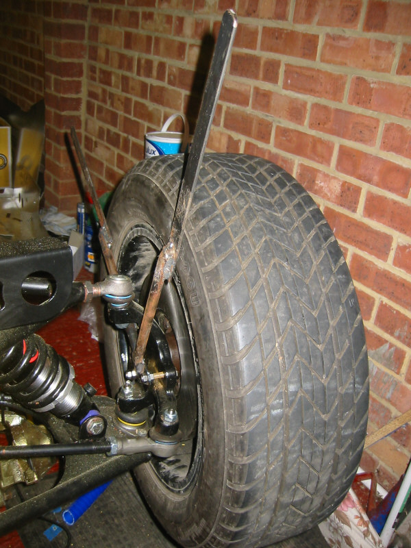
Cycle wing bracket before bending into shape |
'Nearly Finished!' (tm) |
Saturday 7th
Went to Stuart Taylor's to pick up my replacement rear wheel arch, some harnesses, throttle cable and aeroscreen. Also picked up a bonnet air scoop and an in-line water temperature sensor holder. Photos here: Stuart Taylor Motorsport - September 2002
Finished bending the front cycle wing brackets into shape and painted them.
OSF cycle wing bracket |
NSF cycle wing bracket |
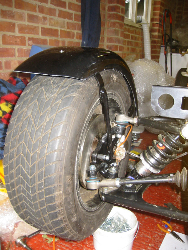
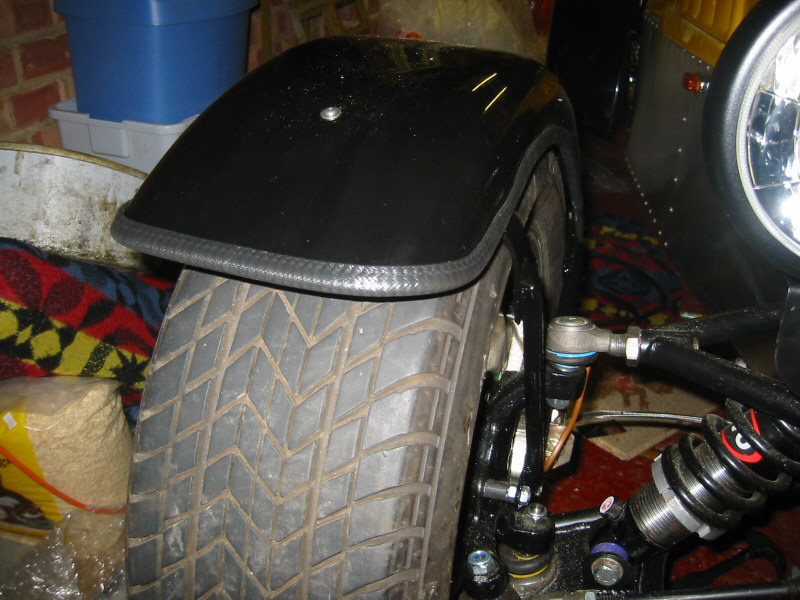
Finished fitting the cycle wings.
Cycle wings fitted |
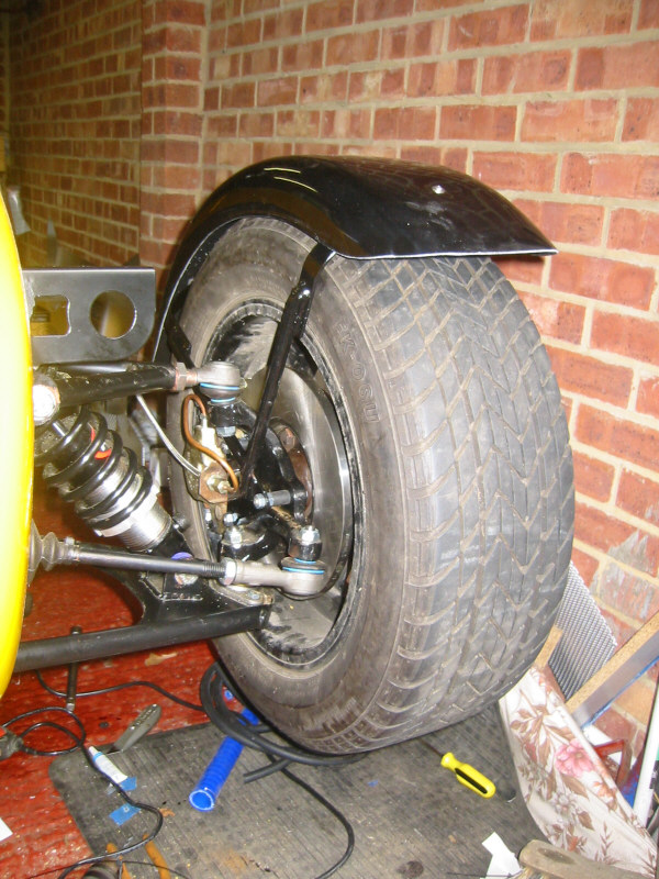
NSF cycle wing |
OSF cycle wing |
NSF cycle wing bracket |
OSF cycle wing bracket |
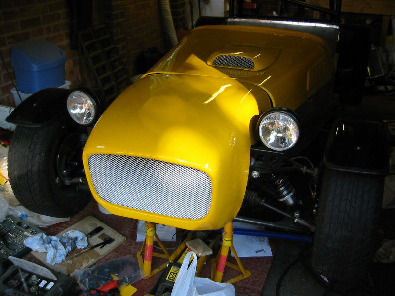
Tested the headlamps and fitted some edging trim to the front cycle wings (SVA requirement). I had 4 metres, but it turned out not to be enough for both cycle wings; I'll have to order some more. You can also see the bonnet scoop in these photos, which will need trimming. The bonnet is sitting proud on one side where the hole for the scoop needs to be cut.
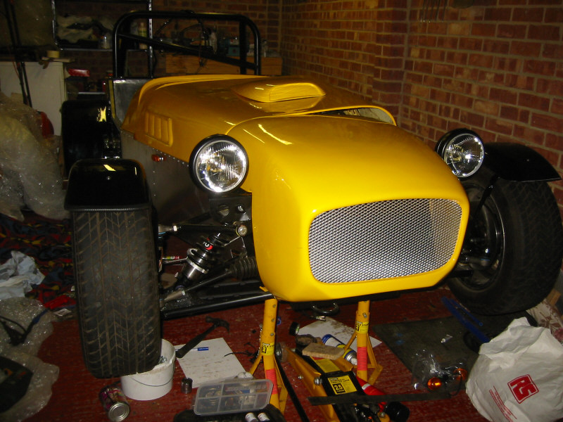
Headlamps fitted |
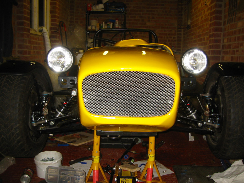
Headlamps from front |
Cycle wing with edging trim |
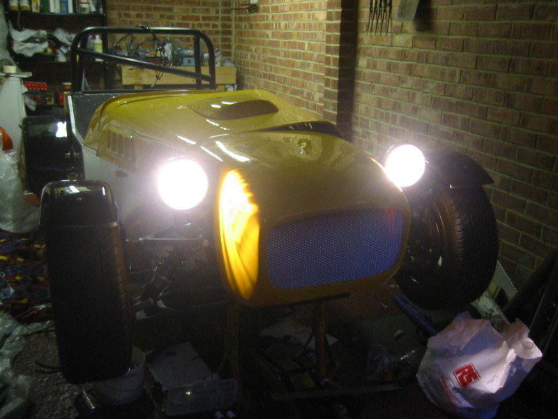
Headlamps on! |
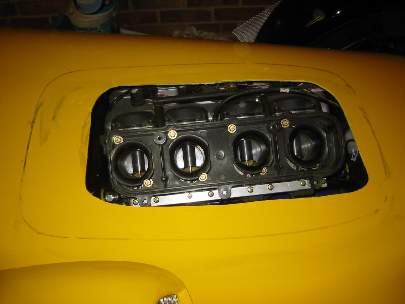
Cut a hole in the bonnet scoop and attached some mesh on the inside. Determined the position of the carbs and cut a hole in the bonnet, gradually enlarging to size.
Hole for bonnet scoop |
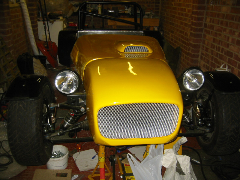
Bonnet scoop trial-fitted |
Last week I sprayed the inside of the wheel arches with anti-stonechip. This should provide some protection to the arches, but also tidies up the appearance. After trial-fitting the nearside rear wheel arch, I marked the positions for the mounting bolts under the arch using some chalk. I drilled holes in the wheel arch first and then refitted to mark the positions for the holes on the body. After drilling the holes in the body, I fitted some wing-piping to the wheel arch using a bit of Sikaflex to prevent it coming loose later. I cut some 'V's in the wing-piping so that it would fit along the curve of the wing more neatly. Finally I attached the arch to the body using stainless steel round head setscrews, nylocs and large repair washers. Once attached, the wing felt very solid. Happy with this method, I then proceeded to fit the offside arch.
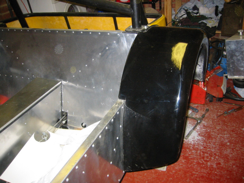
Nearside rear wheel arch
Sunday 15th
Trial-fitted the tunnel top panel. I've folded the sides over and covered the edge with some rubber trim that came in the Westfield SVA kit. I'm planning to fit the panel from the top using small rivnuts, so that it will be removable.
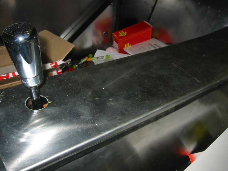
Tunnel top panel trial-fit
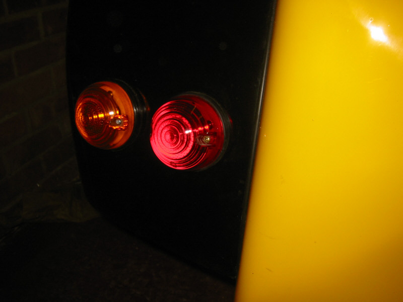
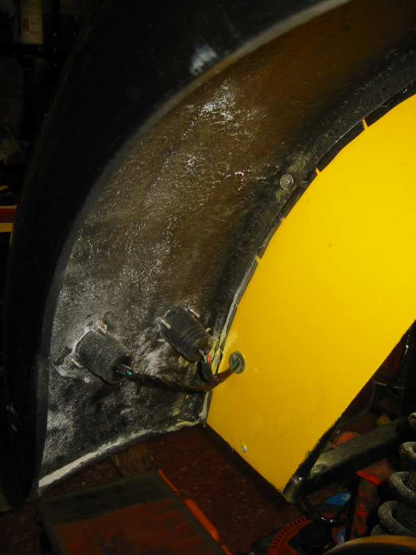
Fitted the rear indicators and stop/tail lamps.
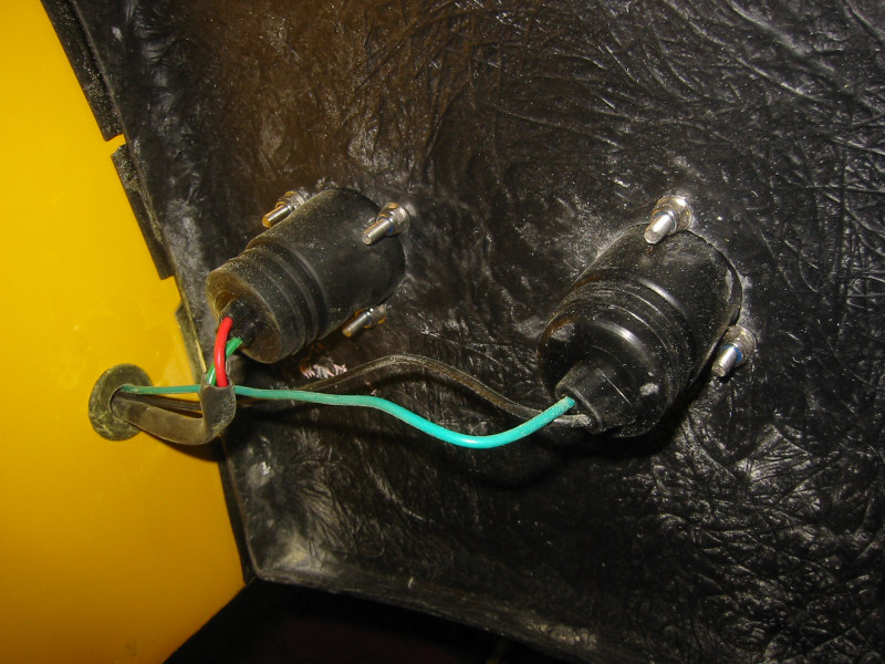
Nearside rear lamps from inside wheel arch |
Nearside wheel arch with lamps |
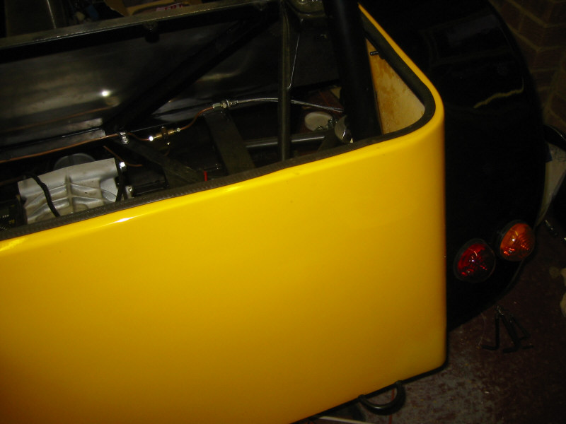
Offside wheel arch with lamps |
Nearside rear lamps from inside wheel arch |
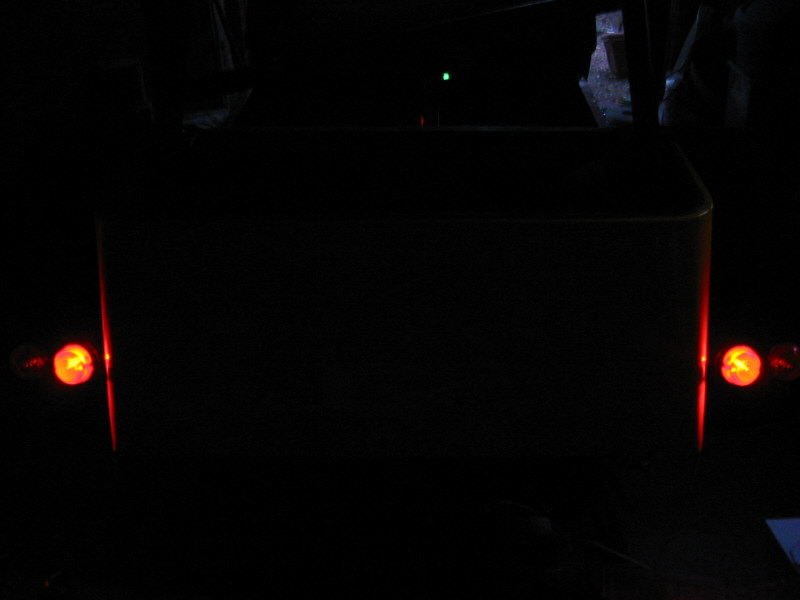
Rear lights on! |
Fuel tank plumbing Exhaust exit hole
Exhaust mount
Fit exhaust
Front indicators
Rear no. plate light
Bonnet/nosecone fixings
Mount scuttle
Make bracket for speed sensor
Fit tunnel top panels
Mount seats and harnesses
Doesn't sound like much does it!
Saturday 21st
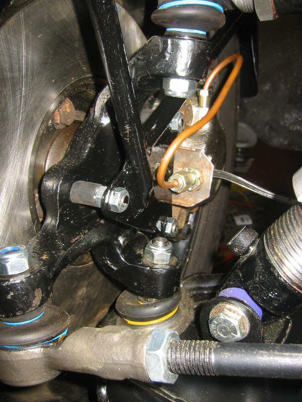
Before I could fit the tunnel panels, I needed to fit the wheel speed sensor. The sensor works by detecting a ferrous object as it moves past. The instructions suggest aiming the sensor at a nut or bolt on a non-driven wheel (to prevent false readings due to wheel spin) but I could see no practical way of mounting the sensor on the front hubs. I considered pointing it at the propshaft bolts, but these are not evenly spaced around the prop, so I decided the best place to fit the sensor was aimed at the rear driveshaft bolts on the diff. I made a template for the bracket, from easily-bendable aluminium and when it was right, I copied it in some thicker steel I found at B&Q.
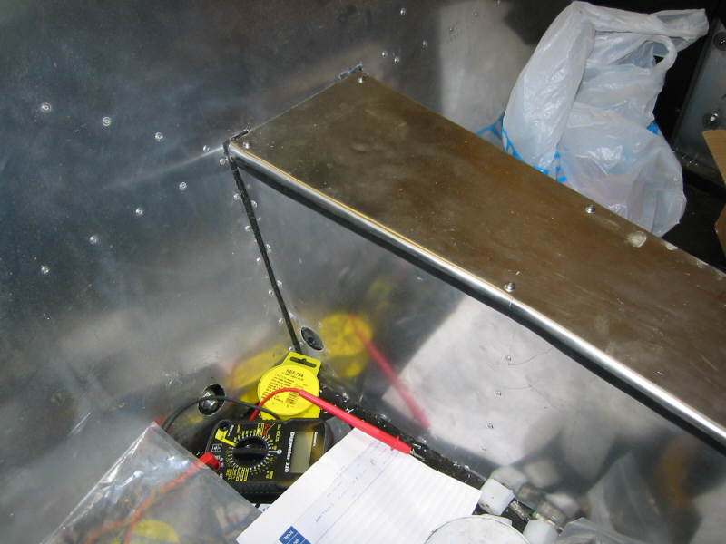
The sensor must be positioned 1 - 1.5mm away from the moving bolts. With the Stack turned on, you can test the sensor as it has a little LED which lights up when it detects a ferrous object.
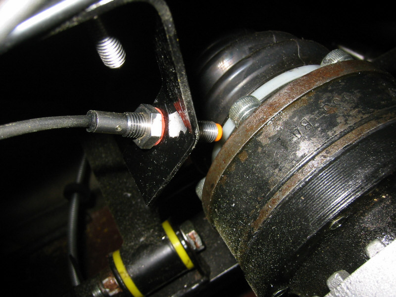
Speedo sensor and bracket |
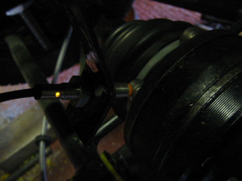
Test light illuminates when a ferrous object (driveshaft bolt) is detected |
When I fitted the first rivnut, I promptly broke the 6mm mandrel on the rivnut tool. Bugger! (Tip of the day no.3: Don't apply too much force when fitting rivnuts). There was no alternative but to drive to the toolshop. They didn't stock replacement mandrels so I gritted my teeth and bought the most expensive rivnut tool in the shop, which hopefully won't break. The new one is made by Eclipse in Sheffield and incorporates an adjustable stop to prevent you from squeezing the grips too far. I fitted the rest of the rivnuts with no problem. (Tip of the day no.4: With tools, you get what you pay for).
Rear tunnel panel fitted |
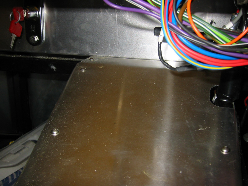
Front tunnel panel fitted |
Finally fitted the scuttle to the chassis. I marked and drilled holes in the scuttle first and then re-fitted the scuttle and marked the positions for the holes in the chassis rail.
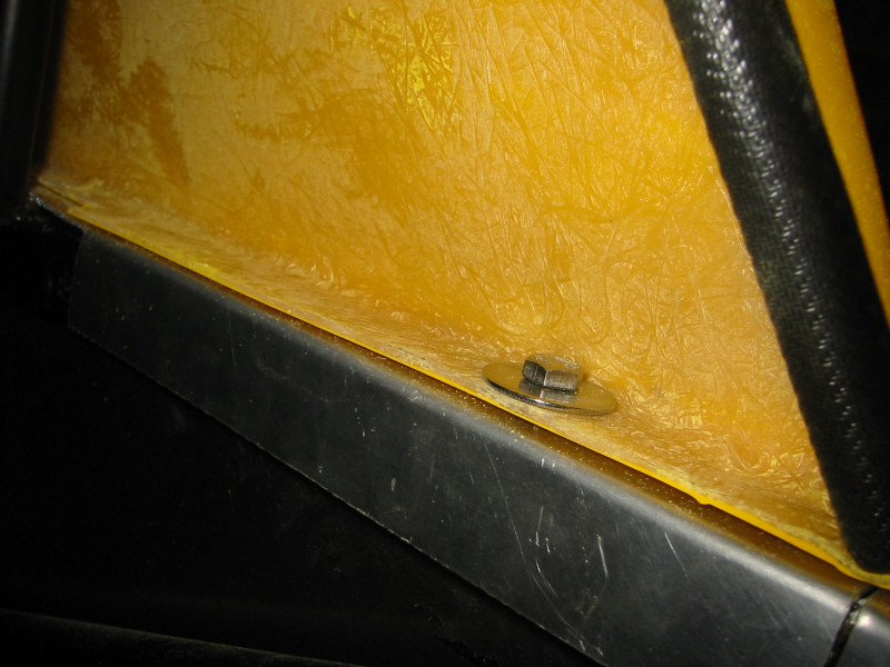
Driver's side scuttle mounting bolts |
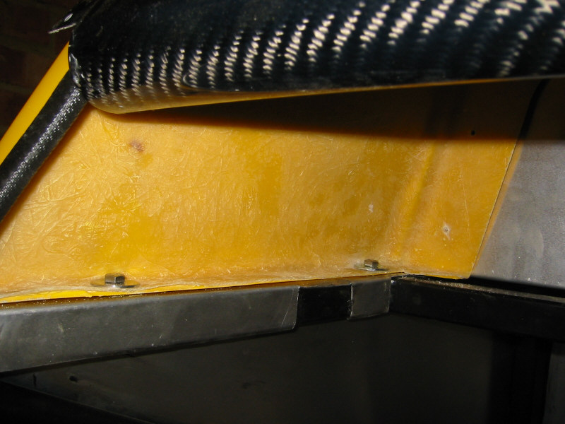
Passenger side scuttle mounting bolts |
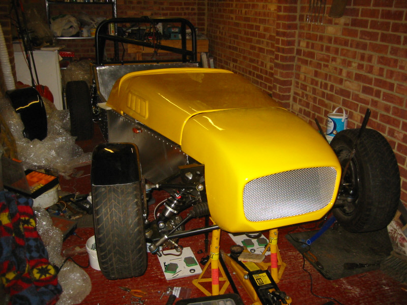
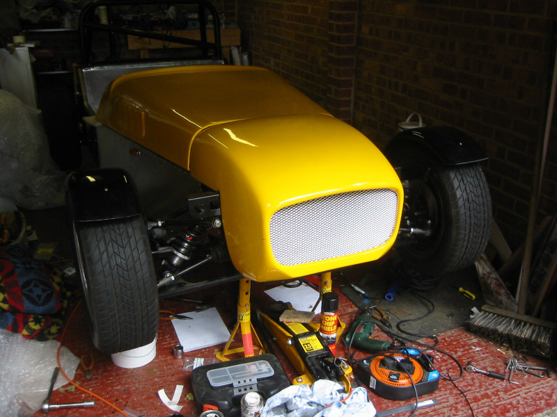
Current status! |