July 2002 - Page 2
July 2002 - Page 1Sunday 21st
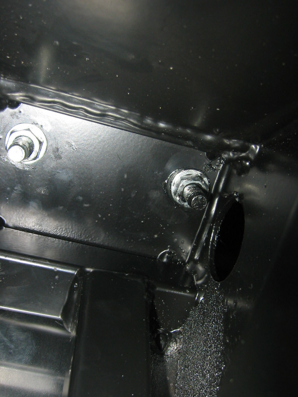
Trial-fitted the exhaust manifold and took lots of measurements in preparation for cutting the exit hole in the side panel. Trial-fitted the rear bulkhead panel and cut holes for the handbrake guides and to enable access to the lower wishbone bolts. At first I tried using a 'drillsaw' drillbit, but it didn't work very well so I reverted to the old-fashioned 'drill lots of holes and finish off with a file' method. Also, finally bolted down the rollbar!
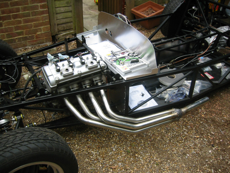
Trial-fit of exhaust manifold |

Holes cut in rear bulkhead panel to allow access to lower wishbone bolts |
Detail of holes in rear bulkhead panel |
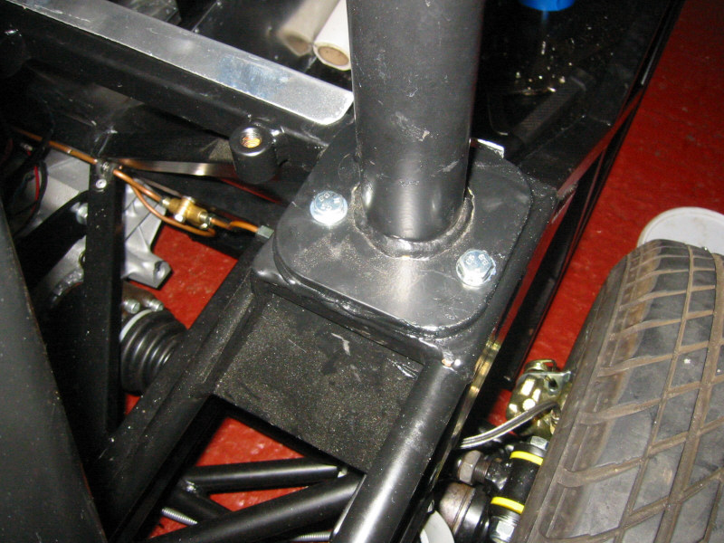
Rollbar bolted to chassis |
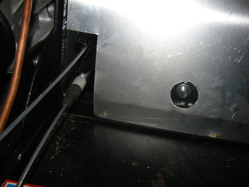
Rollbar mounting bolts from underneath |
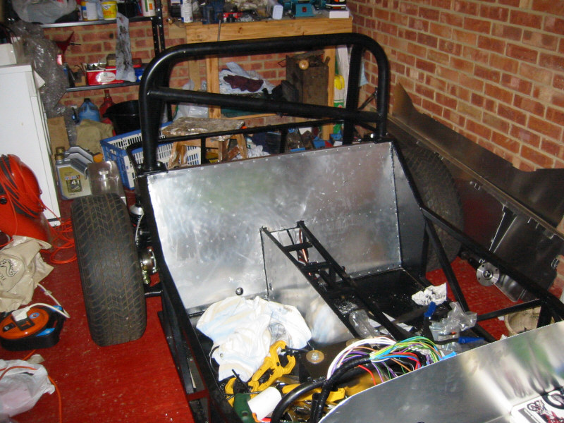
Rear bulkhead panel rivetted in position |
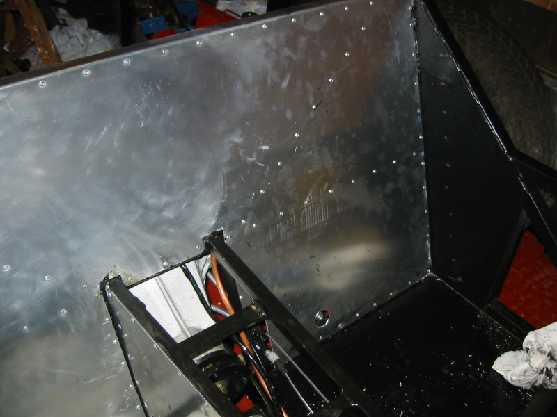
Rear bulkhead panel rivetted in position |
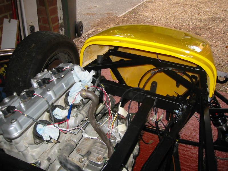
Nosecone from engine bay |
Tuesday 23th
Trial-fitted the prop. It was slightly too long, even with the 'slidey' bit at its shortest position. I may be able to move the diff back a few mm, but if not I will have to get a shorter prop made up.
Wednesday 24th
Managed to re-position the diff about a cm further back in the chassis by drilling new holes in the rear mounting brackets. Trial-fitted the prop again and everything looks good.
Thursday 25th
Phoned Ian at ST about the prop and he said that the diff does need to be positioned as far back as possible for a ZX-9R installation, however, he said he would exchange the prop if necessary. Bought 27mm and 32mm sockets to tighten up the prop flange nut. The Haynes manual says that the sprocket nut should be tightened to 125Nm (what happened to good old lbft?) so I assumed this would also be right for the prop flange adapter in the 4-wheeled version. I fitted two of the prop bolts and jammed a screwdriver between them to enable the appropriate torque to be applied to the flange nut.
Ordered an SVA manual from the Vehicle Inspectorate Agency.
Friday 26th
SVA Manual arrived. Who says the government is not efficient? (I do actually...) It even has a picture of a Westfield on the cover. I have to say, it is very well laid out and easy to understand and there is nothing so far that I am worried about on my car.
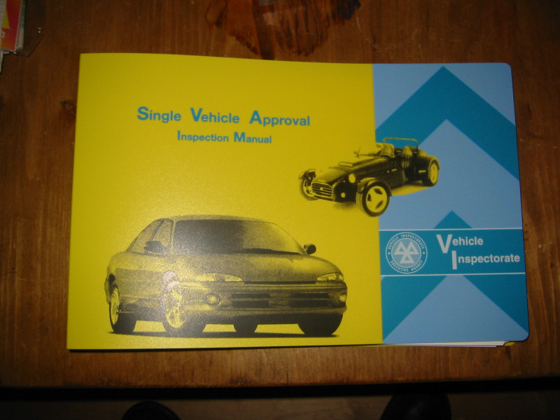
SVA Manual
Saturday 27th
Fitted the prop centre bearing mount and then the prop itself. One of the allen bolts on the front flange proved difficult to access due to the proximity of the UV joint bleed nipple. I used a 6mm ring spanner on a shortened old allen key to tighten this bolt.
Fitted the fuel pipe.
Fitted the gear linkage. The ball joint must be removed from the original gear linkage lever (the bit that fits over the splined gearchange shaft) so that it can be bolted to the rosejoint on the new linkage. For a typical one forward, five back gear change, the splined lever must be positioned pointing upwards on the gearbox shaft. If you prefer one back, five forward (like Ian Gray does!) then position the lever pointing downwards. The linkage must be assembled and positioned from the gearbox back. I temporarily fitted the gear linkage pivot column to the bulkhead with tape to determine the optimum position and the lengths for the rods in the rest of the linkage. After much experimentation and measuring, I marked the position and drilled the holes for the mounting of the pivot column. I positioned the column as close to the edge of the bulkhead as possible so that one of the mounting bolts would pass through a chassis rail thus providing a solid mounting.
Next I trial-fitted the long rod that runs from the top of the pivot column to the bottom of the gear lever to determine ideal length for my preferred gear lever position. This involved the first time I had actually sat in the driving position (and made brum brum noises!) Once I had decided on the position, I marked and drilled holes in the tunnel chassis rails through which to bolt the gear lever. At this point I realised that I will have to fit the passenger tunnel side wall before I can bolt the gear lever in place, as the bolt will go through the panel as well as the chassis rail. That will be the first job tomorrow!
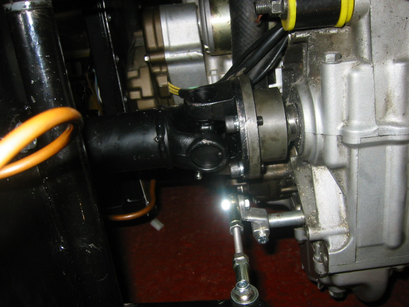
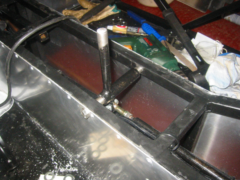
Prop flange adaptor and gear linkage |

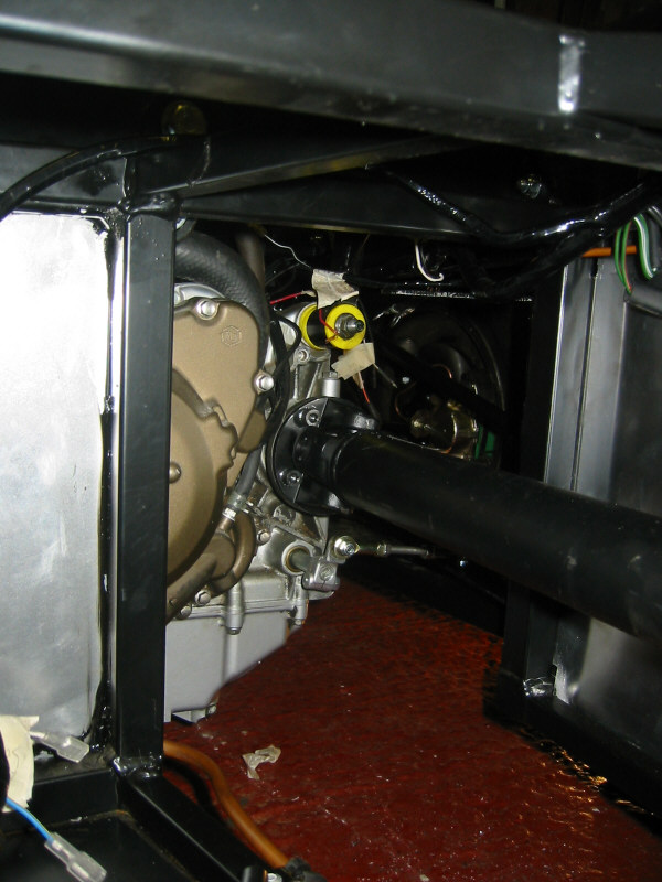
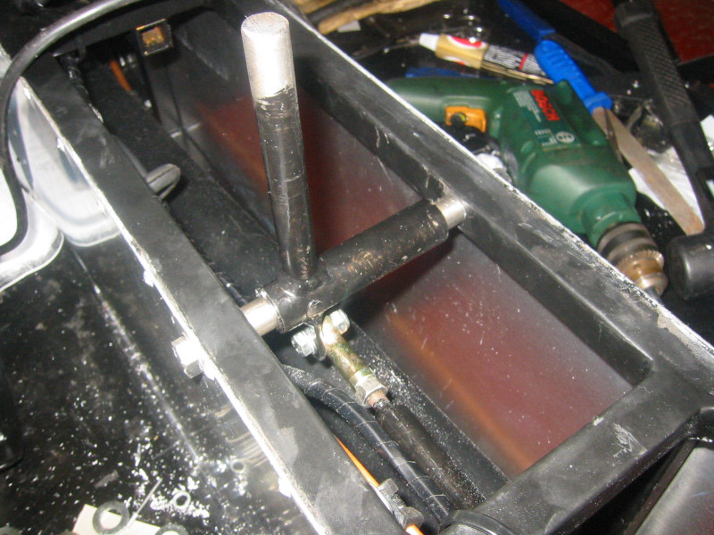
Gear linkage showing bottom of 'pivot column'. I aimed to get the rod connecting this to the gearbox shaft lever as horizontal as possible |
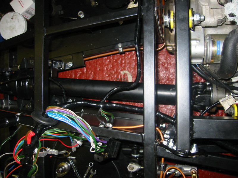
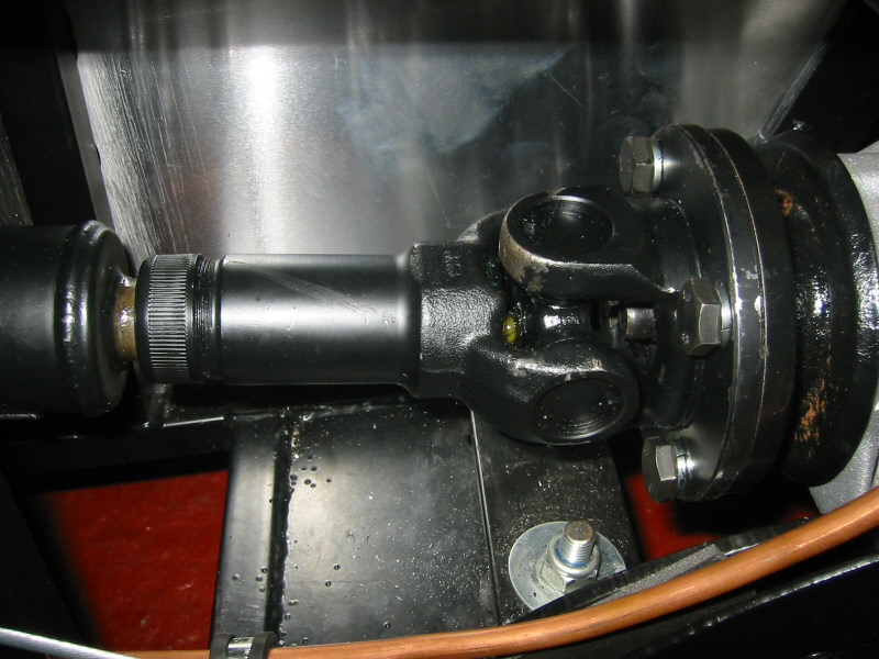
Prop front section. To the left you can see the centre bearing and to the right the prop flange adaptor. The recently fitted copper fuel pipe can be seen toward the top of the picture. |

Prop rear section showing diff flange |
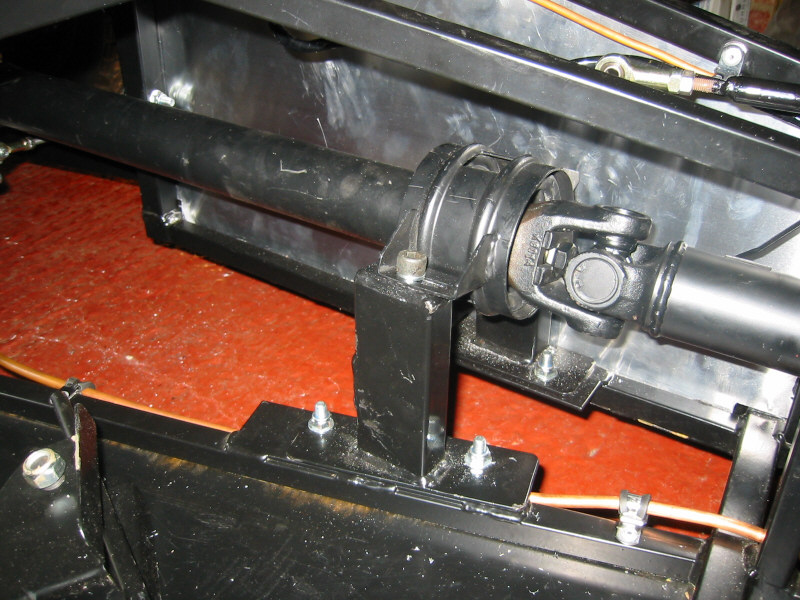
Prop centre bearing. I have positioned this as far right as possible to give the shallowest possible prop angles. |
Prop front section from behind |
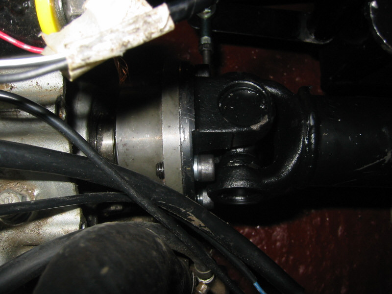
Close-up of rear UJ showing prop sliding section |
Close-up of front UJ |
Sunday 28th
Once the prop, brake pipe, loom and fuel pipe were in place, I was able to fit the passenger side tunnel panel. Once fitted I was able to fit the gear lever. Testing the change revealed a very responsive linkage without any slack, success! However, I noticed that the whole engine was rocking slightly under the force of the gear change. This turned out to be a an engine mount which was not fully tight. It was one of the mounts already fitted by ST, so I checked all the others and everything was fine. Must remember to check EVERY bolt before hitting the road...
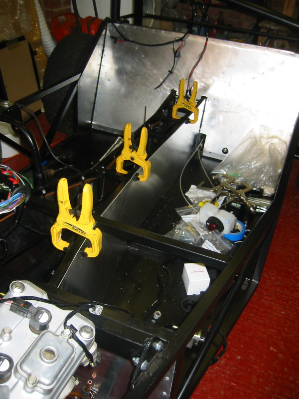
Passenger side tunnel panel clamped ready for drilling |
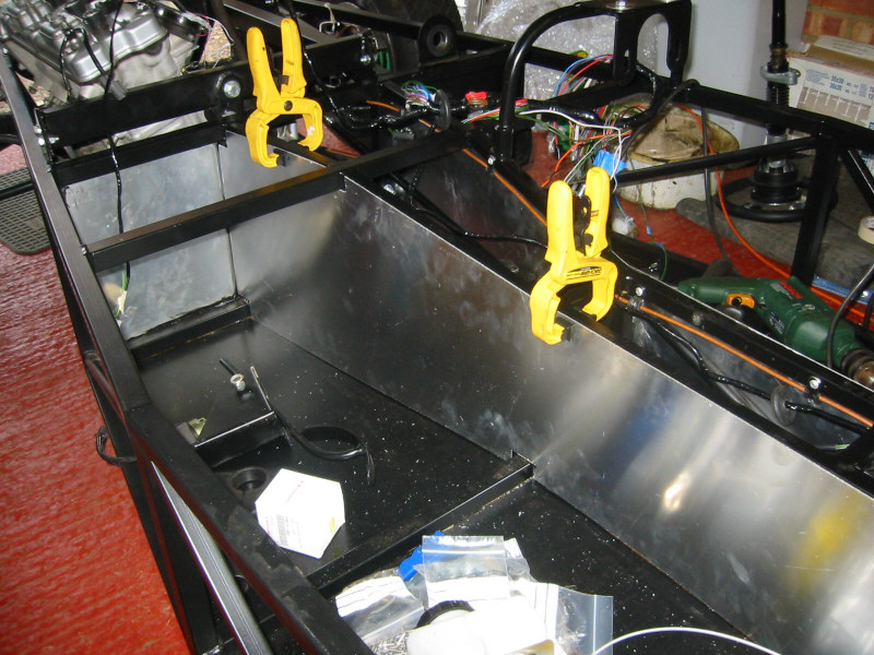
Alternate view |
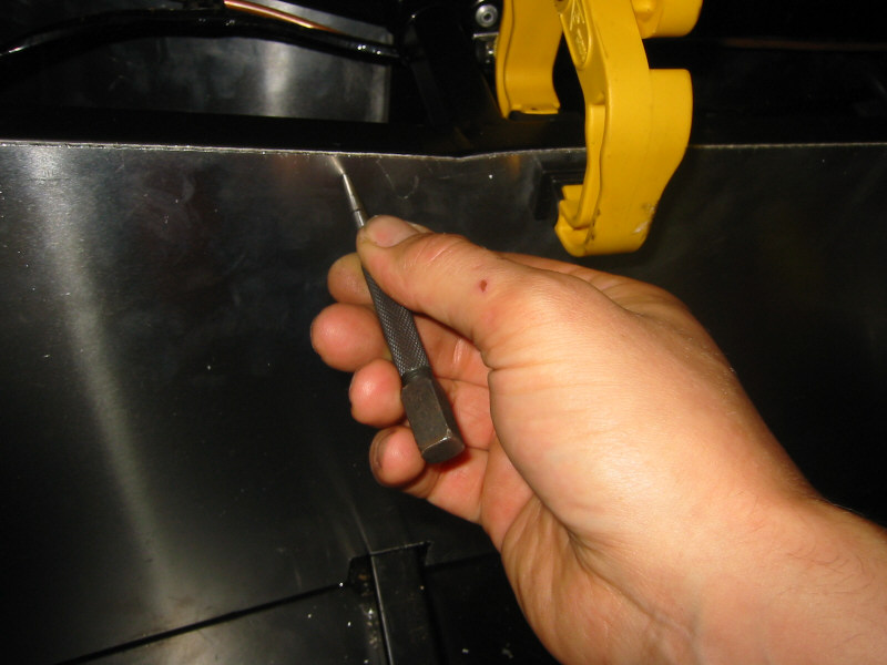
Top Tip 1: Using a dot punch to mark the position of the rivet holes by hand makes drilling easier |
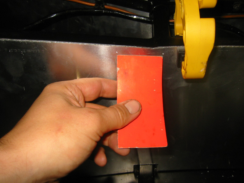
Top Tip 2: Cutting a piece of card 5cm wide makes it easy to position your rivet holes |
Gear lever in position |
Alternate view |
Tuesday 30th
My Stack ST700 dash display arrived today. I looks the dog's danglies! It has some great features including mph/kmh speed display, odometer and tripmeter, voltmeter, 0-60 and standing 1/4 measurement, intelligent alerts, programmable shift lights and oil pressure and water temperature with the additional solid state sensors. It can be upgraded to record manual (button) or automatic laptimes (using a trackside beacon) and full data-logging. Just need a dash to fit it to now.

(Clockwise from top-left) Pressure sender for oil pressure, main harness, temperature sensor for water, sensor harness, rotary control knob, manual, installation kit.
July 2002 - Page 1